Concrete Wall - Seismic Design
Concrete walls can now be designed for seismic design provisions. Here the process is described.
Seismic Design Rules
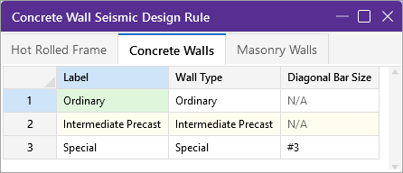
ConcreteWall Seismic Design Rule
|
Column |
Description |
|---|---|
| Label |
The label is the name for the Wall Seismic Design Rule that is called out for a wall panel. |
| Wall Type |
These are the three wall types supported in RISA-3D. |
| Diagonal Bar Size | This specifies the diagonal bar size used for shear reinforcement. |
The following are the three possible states for the Label and Wall Type columns.
-
Ordinary: This option adds no extra checks to the wall on top of the regular code checks for a non-seismic consideration per section 18.2.1.6(b). The provisions required to be met are elements not considered in the RISA-3D analysis/design.
-
Intermediate Precast: This option has provisions specific to wall piers per section 18.5. This Wall Type assumes Seismic Design category D, E or F.
-
Special: This option has provisions specific to section 18.10.
Shear Force Amplification in ACI 318-19
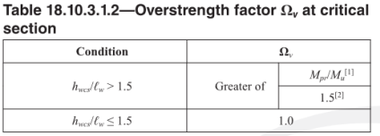
ACI 318-19 Section 18.10.3.1 requires the special concrete wall to consider the design shear force amplification per Equation (18.10.3.1). RISA calculates the amplification factors Ωv and ωv automatically based on the code provisions. The governing Ωv and ωv values are provided in the wall panel/region Detail Report. These amplification factors are used to calculate the seismic design force Ve. Note that the combined amplification factors shall not exceed 3.0 per Equation (18.10.3.1).
![]()
Ωv is calculated per Table 18.10.3.1.2. RISA assumes the lowermost wall panel/region base to be the critical section. In the table, the hwcs refers to the height of the entire structural wall, and lw is the width of a wall panel/region. Mpr is the moment capacity calculated assume steel yield stress is 1.25*fy. The governing combination of Mpr/Mu will be used to calculate Ωv factor. For the wall panel/region at critical section, Mpr and Mu values are reported in the Region result of the Detail Report.
ωv is calculated per Equation (18.10.3.1.3), the number of story above the critical section ns is user-input parameter in Global Model Setting-Seismic Tab:

Click on image to enlarge it
Pier Design
Pier design is governed by section 18.10.8. Section 18.14 is not considered. This design consideration is applicable to ‘Intermediate Precast’ and ‘Special’ shear wall types. To determine whether to perform pier checks we use the pier dimensions from Table R18.10.1. Piers must have vertical edges that meet at a wall edge or opening.
The wall below has four piers.

Click on image to enlarge it
The program is checking the reinforcement in the piers based on Section 18.10.8.1, which references section 18.7.4, 18.7.5 and 18.7.6. If any of these cases gives a failure we will give red text in the detail report regarding this. Specifically, the program checks:
- Rho-min/rho-max per Section 18.7.4.1
- Defining closed hoops per Section 18.7.5.2.a
- Max spacing of vertical bars per Section 18.7.5.2.e
- Cross ties required per Section 18.7.5.2.f
- Max spacing of horizontal bars per Section 18.7.5.3
- Rho-min horizontal per Section 18.7.5.4.
- Wall pier shear checks per Section 18.7.6.1.1.
- Ve = 2*Mpr/Hp. Mpr is calculated using fye = 1.25*fy.
- If Vu < Ve, use Ve. Otherwise, use Vu.
-
If (Ve / Vu) > 0.5 and Pu < Ag*f’c/20 then Vc should be taken as zero per Section 18.7.6.2.1.
Coupling Beams
Coupling beam design is governed by section 18.10.7 and is applicable to the ‘Special’ shear wall type.
Specifically the program checks:
- The program uses a threshold of L/H of 4. If L/H > 4 there will be no design and you must manually design the coupling beam per Section 18.6. If L/H < 4 then the program will design the coupling beam using diagonal reinforcement.
- Vn per equation 18.10.7.4.
- Reinforcement checks per Section 18.10.7.4(d). Section 18.10.7.4(c) is not used because (d) is simpler.
- Reinforcement must be "Each Face".
- Outer bars must be "Horizontal".
- Rho-min as the max of (i) & (ii) per Section 18.10.7.4(d).
Boundary Elements/Zones
Boundary zone checks are based only on section 18.10.6.3. The program performs a check of the maximum extreme fiber compression stress for the worst-case earthquake load combination. If this value exceeds 0.2*f'c then a boundary zone is required. The program will currently tell you if a boundary zone is required or not. It will not design for the provisions of the boundary zone.
Reinforcement Limits for Regions
These checks are for regions that are outside of pier locations.
Specifically the program checks:
- Rho-min Vertical and Horizontal per Section 18.10.2.1.
- Vertical and Horizontal max spacing per Section 18.10.2.1.
- Bar location based on H/L per Section 18.10.2.2.
- Vn-max per Section 18.10.4.1 and 18.10.4.4.
- Rho-min Vertical > Rho-min Horizontal based on H/L per Section 18.10.4.3.
- Rho-max Vertical per Section 18.10.6.5a.
Design Spreadsheet Results
Wall Panel Seismic Detailing
Results for Seismic Detailing checks are provided in the Wall Panel Design spreadsheet - Concrete Seismic tab. Results are provided per region, and the Seismic Detailing column provides a summary of the Seismic Detailing checks. For a more detailed output, check the “Seismic Detailing” portion of the Wall Panel Detail Report.

Click on image to enlarge it
Concrete Wall Panel Seismic Code Checks
|
Column |
Description |
|---|---|
| Wall Panel |
The Wall Panel column displays the concrete seismic wall panels defined in the model. |
| Coupling Beam/Wall Pier | The Coupling Beam/Wall Pier column displays whether the output is for a coupling beam or a wall pier. |
| Region/Pier | The Region/Pier column displays the specific region and the associated pier or lintel. |
|
UC Shear In Plane |
There is one main shear code check for either piers (per Section 18.7.6.1.1) or coupling beams (per equation 18.10.7.4). If the load combination that controlled the design used the overstrength seismic forces (meaning it had an Ω factor in the load combination) then the governing load combination will be followed by an asterisk (*). |
|
LC |
The LC column displays the governing load combination. |
|
BZ Req’d? |
The BZ Req’d? column displays whether or not there are boundary elements/zones required.
|
Reinforcing Spreadsheet Results
Wall Panel reinforcement is provided in the Concrete Reinforcing Spreadsheet - Concrete Wall tab. Results are provided per region. For a more detailed output, check the “Wall Reinforcement” portion of the Wall Panel Detail Report.

Click on image to enlarge it
Detail Report Results
Wall Summary Report
In this report the program gives a color-coded view of the piers and coupling beams in the wall. In the tables the code checks and reinforcement is reported as well.

Click on image to enlarge it

Click on image to enlarge it
Shear Details - Seismic Tab in ACI 318 - 19
When ACI 318-19 code is selected and special concrete shear walls are used in seismic analysis, a new Shear Details - Seismic tab is added next to the regular Shear Details tab. In this tab, the governing Ωv value as well as Mpr, Mu values are presented. The amplified shear demand will be used to calculate the new UC values.

Click on image to enlarge it
Please note that for each wall panel group (a group of seismic concrete shear walls stacked on each other to resist seismic load), the governing Ωv value is used for all panels in this group. There may be multiple wall panels/regions at the critical location which produces different Ωv values, the program only reports the governing Ωv, Mpr, and Mu values in the detailed reports of each wall panel/region.
Wall Summary Report
In this report the program gives a color-coded view of the piers and coupling beams in the wall. In the tables the code checks and reinforcement is reported as well.
Pier Report
In the pier report the program performs a shear code check and gives results for the reinforcement limits required.

Click on image to enlarge it
Coupling Beam Report
In the coupling beam report the program defines the shear check based on the diagonal bars and gives overall wall reinforcement checks.

Click on image to enlarge it